|
Over two weeks during the summer term of school (online university) I decided to design and build a dedicated cart for my two 3D printers. The main goal of this was to have a permanent but mobile printer location off and away from valuable real estate on the workbench. The cart was specifically designed to fit my homemade printer (outlined below in this blog series) and my Flashforge Finder printer. I also built in useful filament storage and a drawer to store hand tools used on the printers.
0 Comments
After being busy for roughly a week, I decided to print another calibration cube to see if the printer kept the z-offset and bed leveling. Upon starting the print, the nozzle basically crashed into the glass plate so I would say no, it didn't keep the values. I knew there were some underlying issues with the Z-axis and keeping its position but I initially hoped it would not be as big of a problem as I thought. However, there is no realistic way to solve it as every time the printer is turned off the steppers lose power and start to "drift", essentially tossing any sort of level or saved offset position out the window. The reason it does this is I have two separate Z-axis stepper motors that rotate independently from each other. I will tackle this problem down below. Otherwise, below is a picture of the attempted second calibration cube once I had re-leveled the bed. As you can see, there was a serious mechanical problem as the location of the nozzle in the picture is accurate to where it was trying to print. 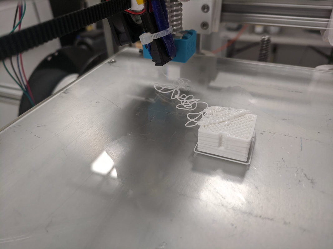 The culprit for the failed print? The set screw on the timing belt backed out and the printer lost control of the X/Y axes. 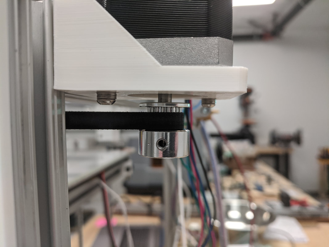 Now back to solving the Z-axis issues... Basically, with the situation I had with the Z-axis, I was left with two options. One, completely redesign it making it a two ACME lead screw design with one stepper motor that controls both lead screws via a belt. Or two, add another limit switch to the second stepper motor currently on the printer. The easiest option to try out was in fact to purchase an additional lever switch and reconfigure the firmware to have two Z-axis endstop switches. By adding another switch, I am creating a decent reference point that the bed can always touch off on assuming the bed isn't warping (it isn't warping significantly but theoretically it does). Every time the printer is turned on and homed it will touch off on both of these switches creating a consistent zero point. This allows for a much more consistent and repeatable bed leveling as the switch's physical positions aren't moving nor are the points on the bed that trigger the switches. To add the new switch into the system I had to hack apart a spare thermistor that had a connector on it that I could just to plug into the control board. This was a very simple task of soldering the two wires onto the switch pins. The harder part was configuring the firmware to do what I wanted. Luckily, Marlin makes it very easy to do this. There were two lines that needed to be uncommented and the endstop logic needed to be changed from true to false (this is just to account for how the switch was wired). The odd thing that happened once I uploaded the firmware and began testing was that each switch was trigger the opposing stepper motor to stop which was entertaining to see. This one didn't need to be fixed in software; I simply flipped the Z_MIN and Z_MAX end stop connectors on the board. Below is a picture of the new endstop switch. 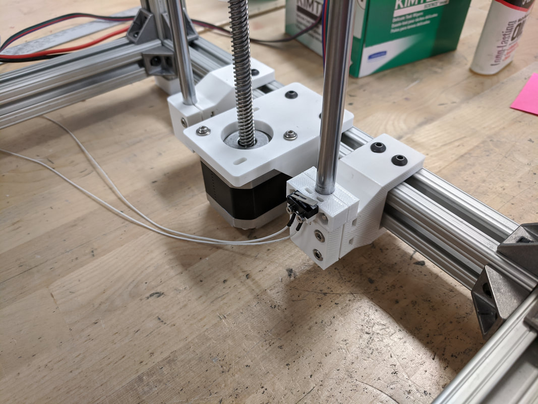 The picture below shows the third calibration cube I printed. This one has slightly better face features as it seems the layers are more on top of one another compared to the first cube. There still seems to be some error though which I think can be attributed to the linear rails and bearings as they are not of the highest quality. Furthermore, the extrusion multiplier should be adjusted because I think it's extruding a little too much plastic. The small nubs on all of the corners can hopefully be removed in the print settings as the slicer, Simplfy3D, has a feature, drift to end, which slows/stops the extrusion before it reaches an endpoint. 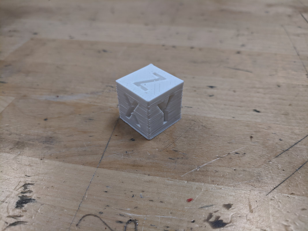 Today, after replacing the stepper motor and readjusting the Z-axis home offset, I was able to try out my first print. I decided to print a calibration cube, as most people do, for the first print so I could see just how off things were. I still do not have the bed heater up and running so it was going to print on the cold glass. I was skeptical of if I would get any bed adhesion but was eager to try it. The first three perimeter layers did not adhere to the bed at all but the first layer infill did, which was surprising. The print was still useless, however, as the non-adhered plastic was now drifting with the nozzle and was most definitely going to jeopardize the rest of the print. I cleaned off the bed and applied some glue to the glass to get the first layer to stick. This time the first layer adhered perfectly. 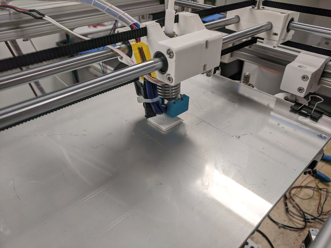 Here is the finished calibration cube: 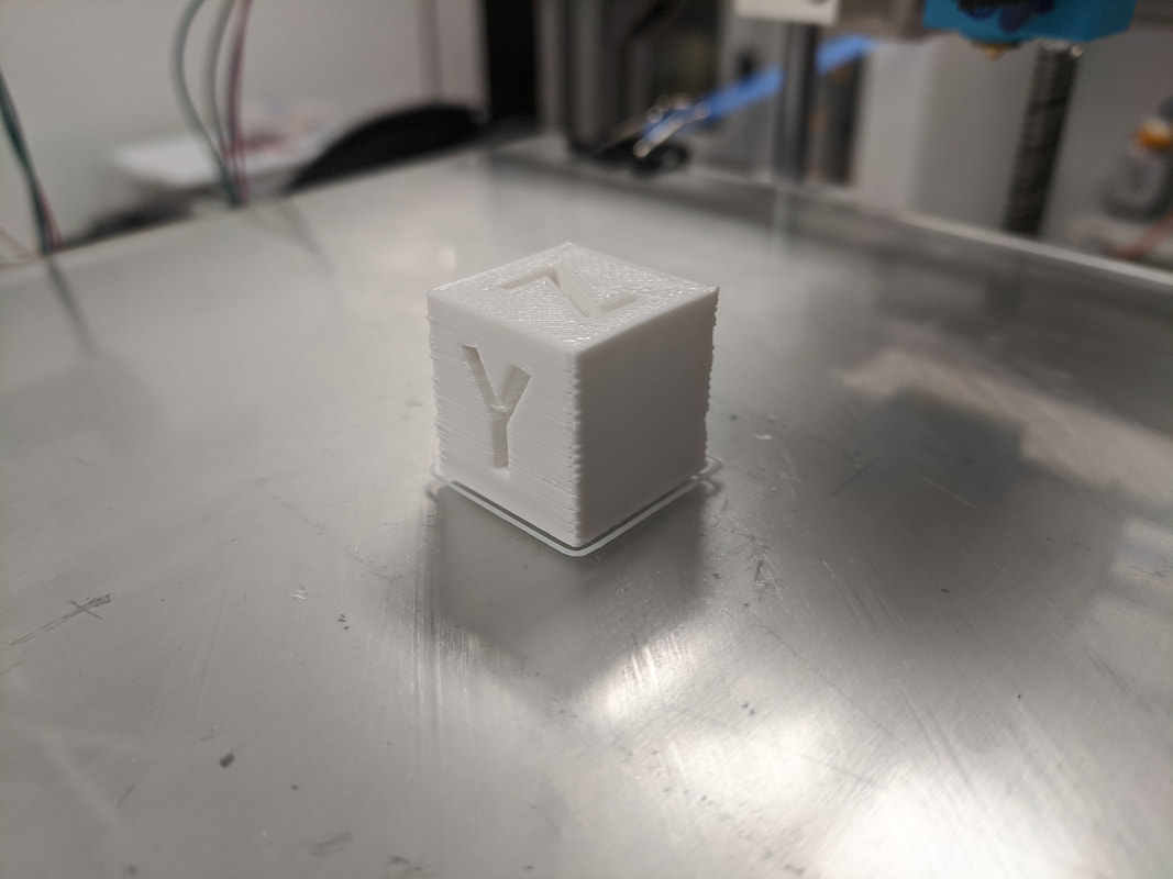 There is still a lot of work to do on all of the axes to bring the accuracy closer to what I want but I'm pretty happy with how this turned out for a first go. From the picture above you can see that it looks like each layer shifted slightly as the print went along. I think this could be the belts not being taught enough. Furthermore, the extruder stepper motor began slipping at one point during the print which I have conclude is because the filament feed rate was too high for the nozzle temperature I was running at. Mid print I bumped up the temperature ten degrees and the problem seemed to go away. The next step is to take a look at the XY-axis carriage system because I believe there can be some adjustments there and to get the heating bed going.
This is related to the last post. I pursued testing the control board further to hopefully solve my problems. The rest of the steppers moved so I was afraid that I had a bad extruder driver on the board. This would have been a real problem because the board I have has integrated drivers so I would have to replace the entire board to fix the problem. I tried some extra steppers I had lying around and those too did not move. The next step I took was to make a break out connector from an extra harness I had lying around as I wasn't quite satisfied I was reading the voltages properly before. I hooked up multi-meters to the break out and recorded the voltages from each of the pins. The driver in question seemed to be performing not out of the ordinary (Online sources showed that if the driver was bad, I would be getting no voltage on any of the four pins). Still the stepper would not move. I shut it down for the day and started entertaining the idea of purchasing a new board.
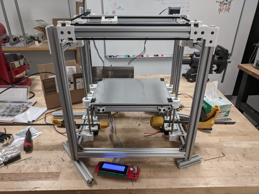
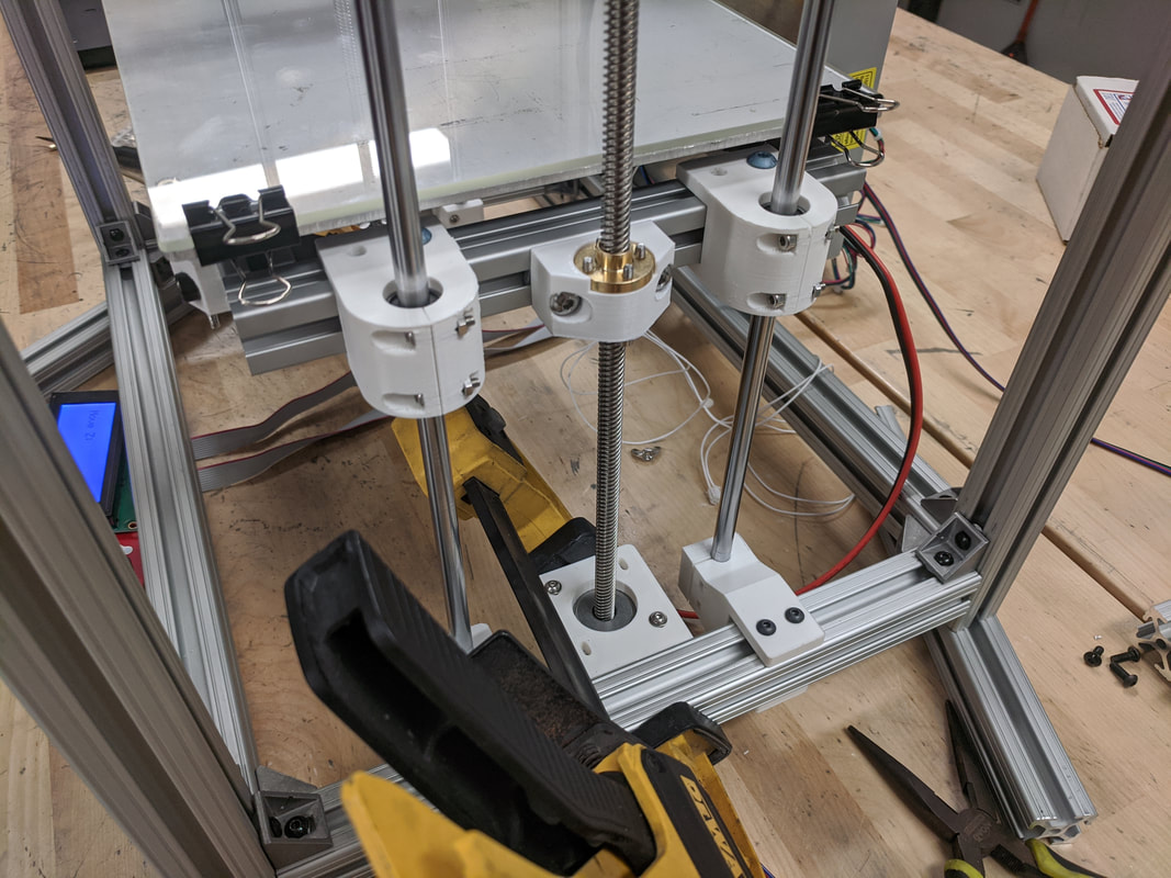
The next day I tried to see one more time if I could solve this problem before I spent money. I plugged the stepper in and noticed I was getting very erratic movement out of it but different than what was happening before. To further investigate, I plugged in a different stepper motor and everything began to work fine. As it turns out, the stepper motor I had purchased with the extruder kit was dead-on-arrival. However, the only explanation I have for why other stepper motors didn't work as well was that the bad stepper may have put the board into a weird logic state and as soon as the board was turned off and reset, that state was reset. I have had no other problems with it in the further tests I ran. After heating up the nozzle to the printer, it was time to test if I could feed plastic from the extruder. In short, I could not. The stepper motor would twitch or spin one way for a little and then randomly reverse directions. At first I thought the stepper motor could have been bad but after plugging it into one of the other axes and it spun just fine. The only other explanation would be that the stepper motor driver is fried which is entirely possible as this board came from an older printer that had a plethora of issues. To do some trouble shooting, I tested the pins with a multimeter but it proved inconclusive as I didn't really know what I was looking for voltage wise. The next step was to check an adjacent driver and check the voltages on those pins. The stepper motor does its micro stepping by varying the current going through the coils. I'm going to check the pin out again but then look at how the current is changing. The micro stepping should follow a sine wave and I hope that I'll be able to replicate that on an oscilloscope if I need to use one. Below is a diagram on how the coils are set up on a 4 wire stepper motor.  This is going to be a long post. I made a bunch of stupid design decisions that ended up working against me. To dive right into it, the first problem I encountered was that the stepper motor mounts for the Z-axis were poorly designed. There was no way to locate the stepper and then tighten the mount to the frame. It became impossible to run the Z-axis in that configuration without risking damage to the steppers or linear bearings due to misalignment. The redesigned mounts had holes on the top of the part to bolt down onto the 80/20 frame. It is now easier to access and change the position of the mount if needed to be adjusted. 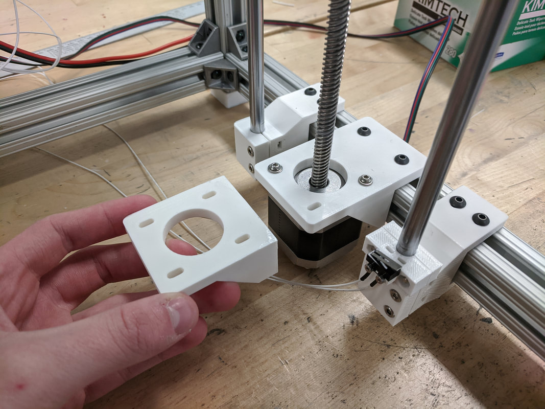 The next design failure was the Z-axis endstop clamp. This time the problem was that it was impossible to get the clamp onto the Z-axis rod without taking the rod clamp/mounts off. These were already very hard to get onto the 80/20 pieces so the fastest solution was to redesign and reprint the endstop clamp. Below is the original endstop clamp design. It is evident that the part was hastily designed as all of the load on the switch is cantilevered out from the clamp point. 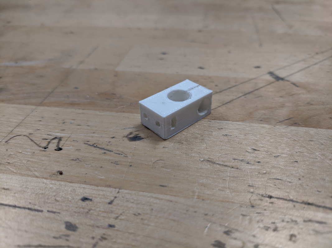 I decided to go with a split clamp design that was mostly symmetrical and had no more cantilevered geometries (technically still cantilevered but the lever arm is now much shorter). Below is the new clamp. 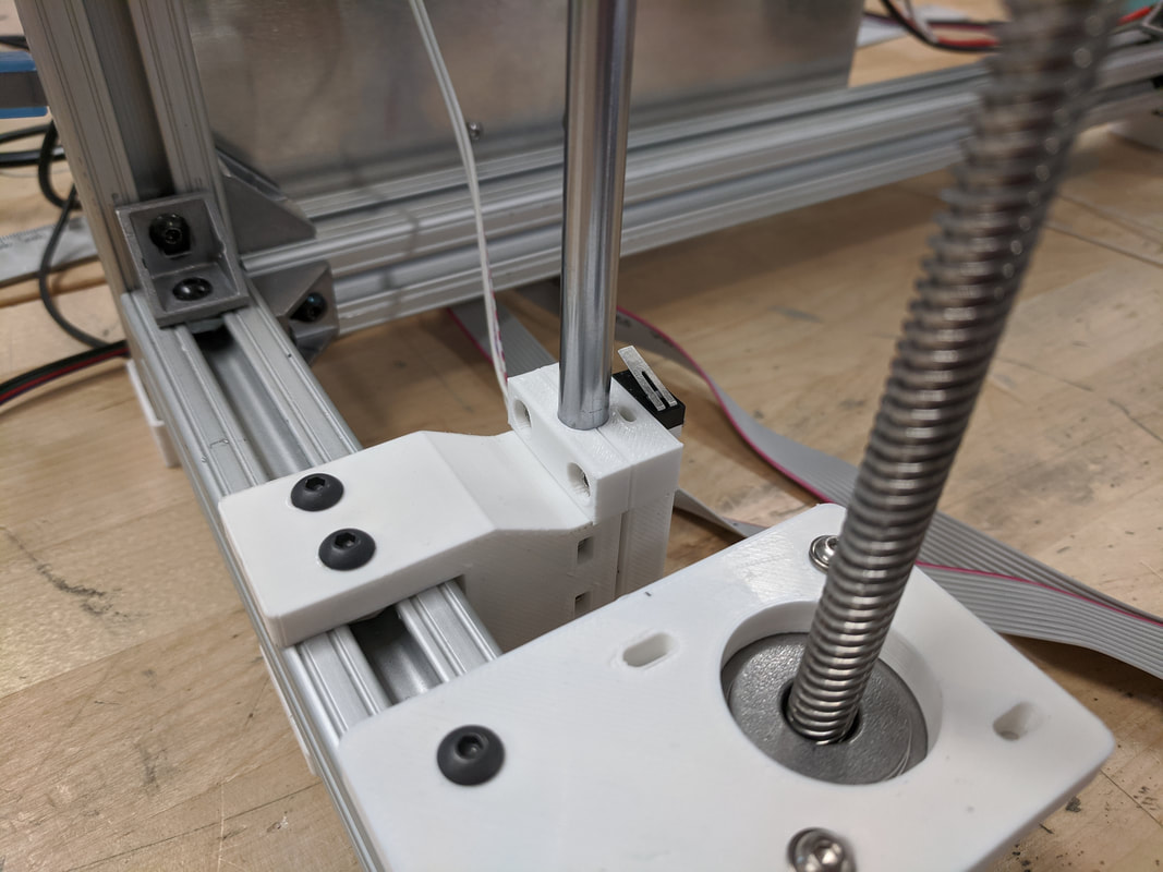 One of the other items that were noted was the fact that the bed had the possibility of getting out of alignment by using two stepper motors. During a couple of the trial runs, the right side stepper would stop occasionally and cause the bed to twist. A solution to solve the problem is to add an additional endstop switch on the right side so when the bed goes to level, it has to trigger both switches to be considered in its Z-axis zero position. However, after some additional testing, the function of the Z-axis was performing satisfactory. A huge challenge I foresaw was configuring the firmware to operate a Core XY printer. While Marlin, the open source firmware I'm using, has many built in features, there were still a few pieces that would probably need a lot of debugging and internet help/research. A big problem I had was getting the extruder fan to run. Most of the time it just would not go at all. Furthermore, the internet suggested that the fan should just be plugged into the 12V power supply so it would run continuously as soon as the printer was powered on. I did not like this as I wanted as much control as possible over the printer's functions. I found a few lines in Marlin that would allow me to change the pinout of the control board and assign the fan pins (D9) to a line in the code that would power up the fan once the hot end got to 40 degrees Celsius. This worked very well and now the fan behaves as I intended it to. I also had to flip the logic of the endstop switches as they were backwards and would not trigger when each of the axes reached the end of their respective travels. The X-axis endstop switch leads were too short to reach the back of the board so I had to break the lines and add in extension wires. This wasn't too much of a problem other than it took time to work on that. The last minor problem that happened was I found that the Z-axis stepper motors were below the lowest point of the frame so the entire weight of the printer would rest on them when on a table. I quickly modeled some press on feet that would bring the printer higher and off of the stepper motors. The picture below shows the new feet. 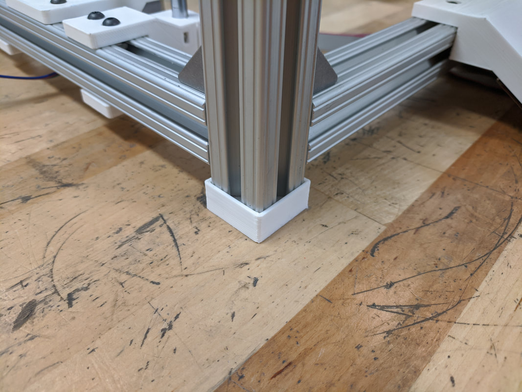 The next logical thing to work on for this printer was the Z-axis. I had put this off until now because I've always had trouble with getting Z-axes to function properly. Whether it was already on an existing printer or designed by me, the Z-axis would fail to work as it is intended. Therefore, in the design phase, I spent a ton of time making sure that the Z-axis would be done right. Below is a picture of the printer in a stable state before I had to start taking frame pieces apart to integrate the Z-axis. 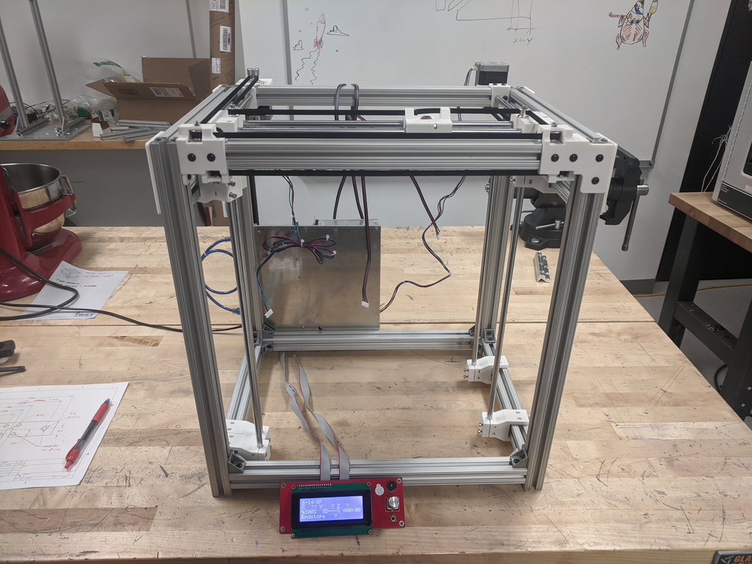 To get the rod mounts that guide the Z-axis into the frame, I had to take apart 80/20 pieces to slide in the C-shaped mounts. While I do use drop in T-nuts, I unfortunately discovered that my M4 bolts were not long enough to "grab" the T-nuts inside the 80/20 channel because of how thick the mount was. Therefore, the rod mounts had the M4 bolts and T-nuts loosely bolted together, going through the 3D printed part, outside of the frame. With the frame section removed I could slide on the rod mount from the end of the 80/20 piece. This was a long a frustrating process but it worked. The image below shows the bed assembly and other Z-axis components fitted to the frame but nothing tightened down yet. 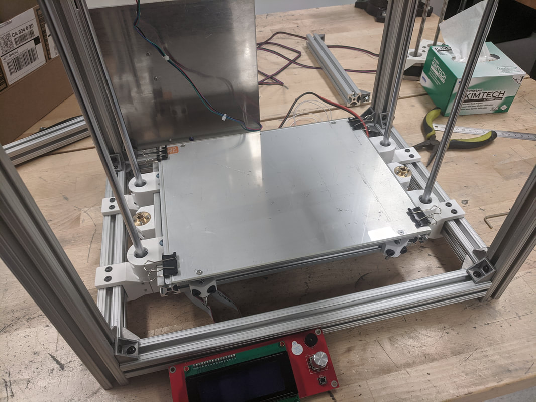 The last two images show how the acme lead screws/steppers were clamped against the frame so I could quickly run some tests on the Z-axis with the control board. At first trial, there was little to no binding and overall good movement, up and down. Good signs.
I've spent the past weekend doing a bunch of test fitting and part assembly to try and get the printer to a point where I could start testing the electronics. The first thing that needed to be accomplished was finishing up the frame and all of the mechanical aspects of the X/Y axes. In the last blog post I showed the redesigned pulley mount. The new design works great and keeps everything pretty square and true. Upon plugging in the board and LCD display for the first time, I found that there were some problems with the firmware on the board as the 20x4 LCD was just displaying blocks across. Unfortunately, the internet was down at where I was working and I couldn't easily work the problem. I took the board and LCD back to my apartment and found that there was just a couple lines in the opensource Marlin firmware that needed to be commented out to get the LCD and control to work. I was satisfied with it's function and deemed it OK to reintegrate with the other electronics. Next up was to start laying out the electronics, cutting wire, connecting stepper motors, testing the hot end and endstops. At first, I laid out the electronics on the bench and just plugged things into the board. I wired up the 12V power supply to the control board and took a look at the LCD. One of the first things I did was to jog the steppers to see if I could get the carriage to move back and forth. It was slightly awkward at first as the carriage only moved diagonally which I couldn't explain in the moment (more on that later). The picture below shows the first electronics setup I had. 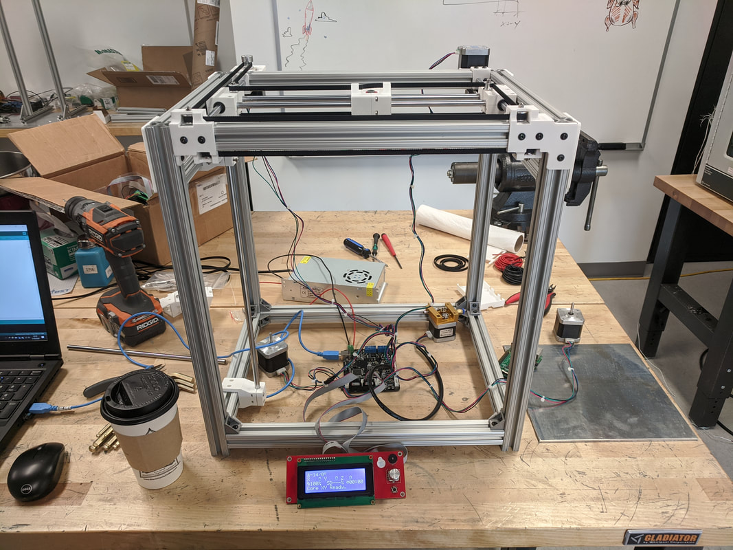 This set up soon proved to make it difficult to troubleshoot because it became a wire nest. The next logical step then was to make the electronics mounting board. The board is simply a 9" x 9" square, 1/8" thick 6061-T5 Aluminum plate. I chose aluminum because I wanted something that was going to be very rigid and look clean. The slideshow below has pictures of how I built the mounting board. Because of the time I spent to get the firmware operational first, the testing process went much smoother than I expected once the mounting board was made and I was able to get the steppers to move the carriage in the X & Y axes properly within a short time. I don't have video at the moment and will upload something in the future. Going back to the weird diagonal movement I witnessed first, I found that the most likely culprit was a loose connection to the left hand side stepper. Errr.
After reviewing the problem I was having with the pulley axle (which was just a M3 bolt), I decided I needed at least two points of contact to keep the axle parallel to the other pulleys and the frame. In the picture below you can see the profile on the new part. I tried to keep the geometry as low profile as I could. I didn't want to have it sticking up very far but I also didn't want this to bend or break. There are also two new mounting points on the front. Since additional plastic was added, I figured it would be beneficial to take advantage of creating two more extrusion mounting points to add to the rigidity of the part. 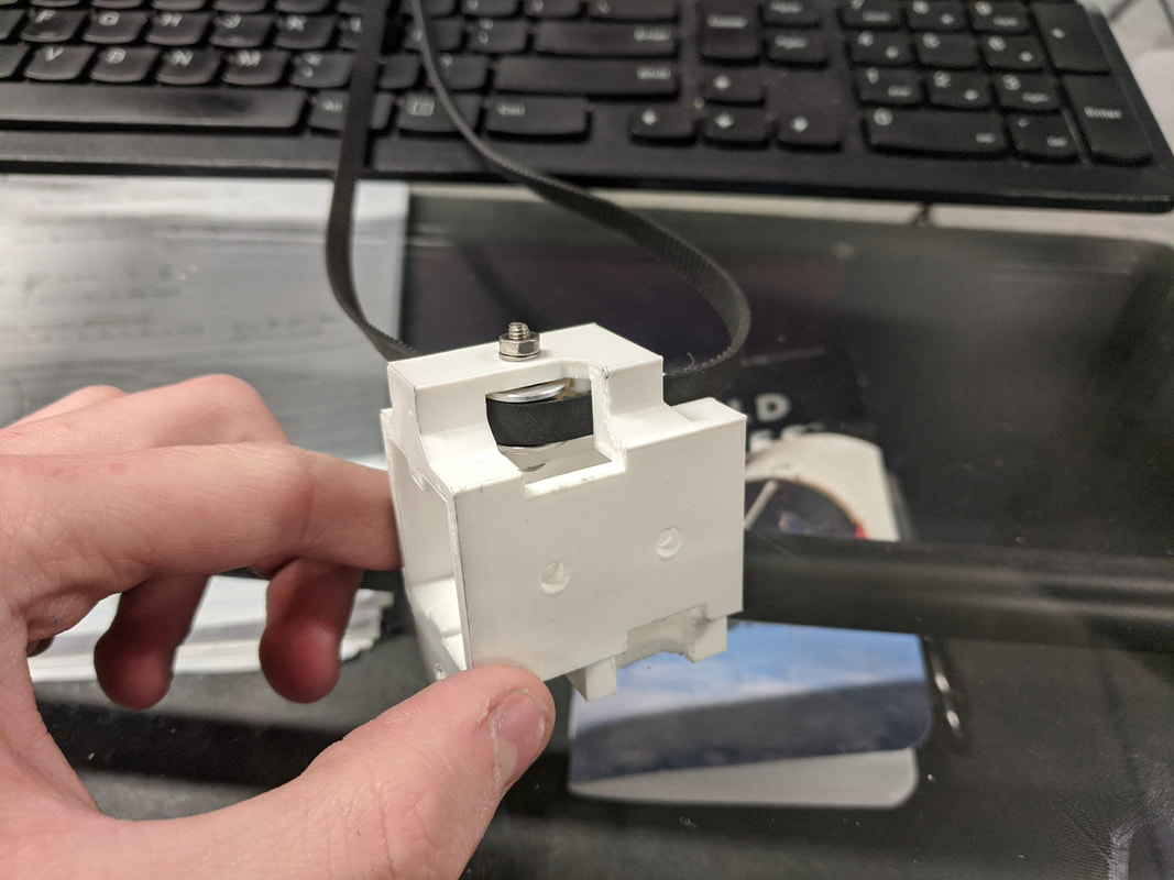 Below is the part integrated onto the frame of the printer and it seems to work great at first trial. The pulleys were running smooth and the belts were operating parallel to the linear rods. 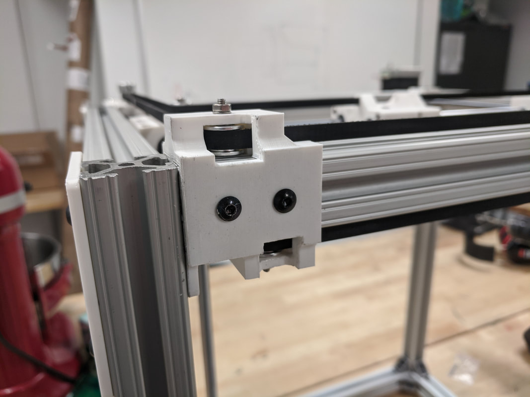 Lastly, below, you can see the difference between the new version of the pulley mount, left, and the old version, right. I do enjoy the look of the new part and I definitely like it's function because it will give me less headaches. 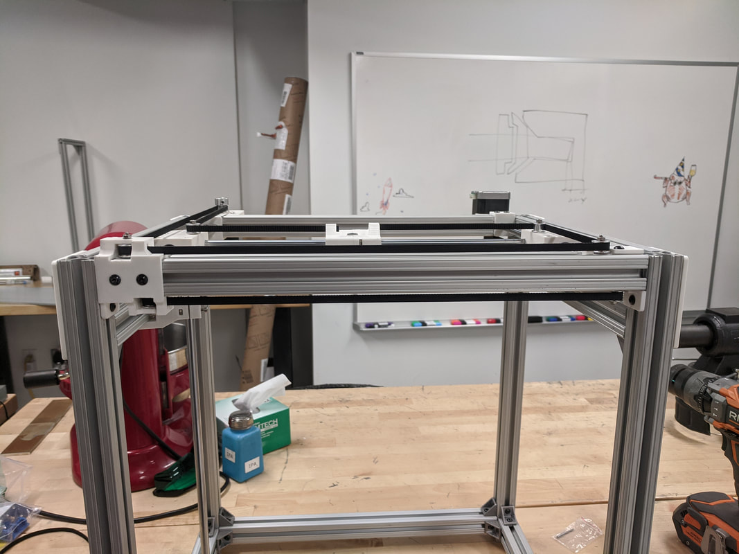 Today became a very troublesome day after numerous parts didn't perform as I thought they would. The first and largest problem was the rail system for the carriage. Upon assembling the XY axes, a substantial amount of slop was found in the 3D printed clamping points. Unfortunately, this is not really fixable as the pieces plastic and are going to deform and flex under loads. I'm going to try and mitigate the problem by possibly beefing up the split clamps. Another major problem was that the carriage assembly doesn't run parallel. This, however, was solvable by adjusting the tension in each of the belts. I was able to adjust the tension enough to get it to run smoother but not enough to eliminate that problem. I plan to come up with a different method to keep a consistent and equal tension on both of the belts so that the carriage isn't twisting on the linear rods. In the picture below, there is a gap between the far side carriage and the rod mount. This will result in uneven wearing of the rods and bearings if not adjusted. 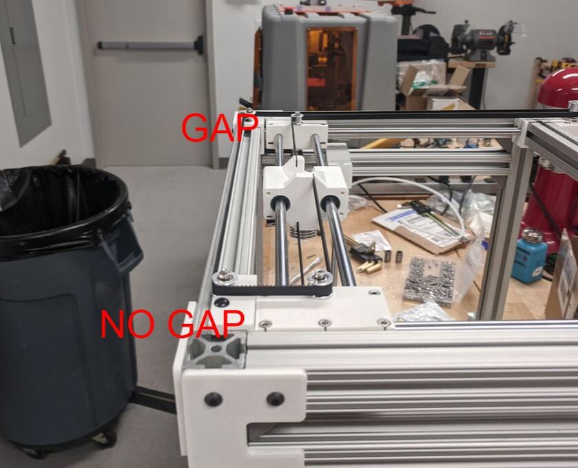 Lastly, the XY Idler mounts need to be redesigned as they severely flex and are destined to break in the near future. The picture below shows how much off axis the idler pulley and bolt are. This is due to the significant tension force in the belts. The last image shows the new solution to that problem which I will be testing soon. The bolt will have two points of contact on the plastic and should stay on axis. 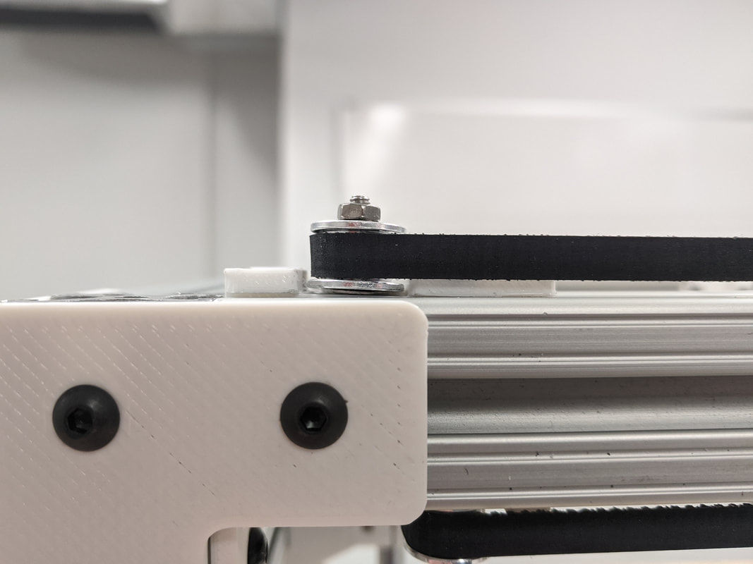 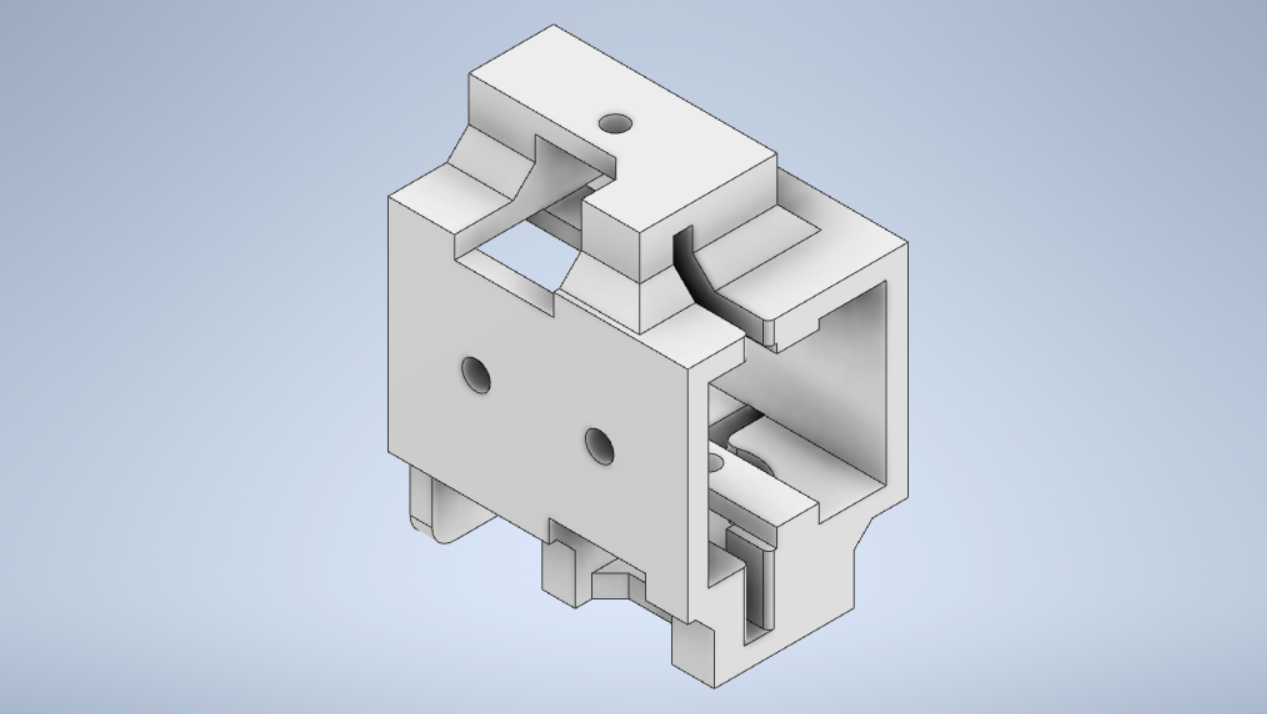 |