|
After being busy for roughly a week, I decided to print another calibration cube to see if the printer kept the z-offset and bed leveling. Upon starting the print, the nozzle basically crashed into the glass plate so I would say no, it didn't keep the values. I knew there were some underlying issues with the Z-axis and keeping its position but I initially hoped it would not be as big of a problem as I thought. However, there is no realistic way to solve it as every time the printer is turned off the steppers lose power and start to "drift", essentially tossing any sort of level or saved offset position out the window. The reason it does this is I have two separate Z-axis stepper motors that rotate independently from each other. I will tackle this problem down below. Otherwise, below is a picture of the attempted second calibration cube once I had re-leveled the bed. As you can see, there was a serious mechanical problem as the location of the nozzle in the picture is accurate to where it was trying to print. 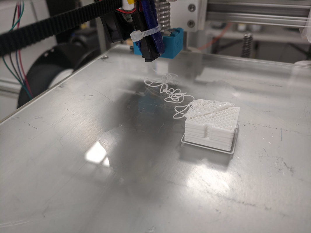 The culprit for the failed print? The set screw on the timing belt backed out and the printer lost control of the X/Y axes. 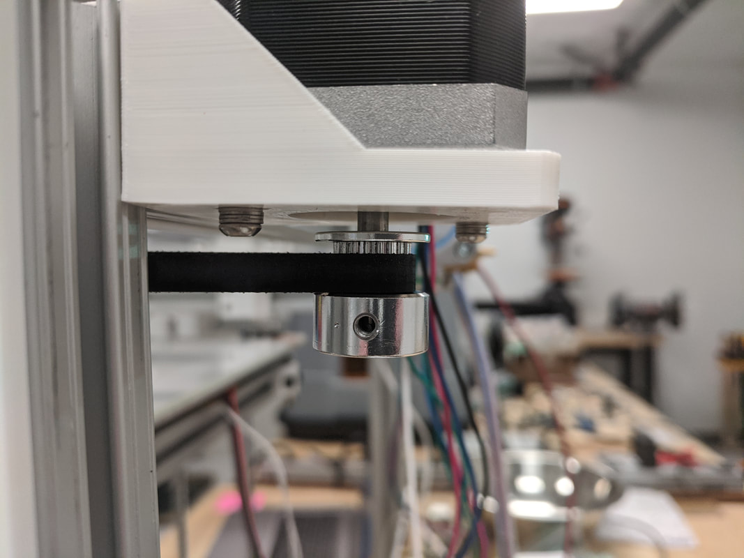 Now back to solving the Z-axis issues... Basically, with the situation I had with the Z-axis, I was left with two options. One, completely redesign it making it a two ACME lead screw design with one stepper motor that controls both lead screws via a belt. Or two, add another limit switch to the second stepper motor currently on the printer. The easiest option to try out was in fact to purchase an additional lever switch and reconfigure the firmware to have two Z-axis endstop switches. By adding another switch, I am creating a decent reference point that the bed can always touch off on assuming the bed isn't warping (it isn't warping significantly but theoretically it does). Every time the printer is turned on and homed it will touch off on both of these switches creating a consistent zero point. This allows for a much more consistent and repeatable bed leveling as the switch's physical positions aren't moving nor are the points on the bed that trigger the switches. To add the new switch into the system I had to hack apart a spare thermistor that had a connector on it that I could just to plug into the control board. This was a very simple task of soldering the two wires onto the switch pins. The harder part was configuring the firmware to do what I wanted. Luckily, Marlin makes it very easy to do this. There were two lines that needed to be uncommented and the endstop logic needed to be changed from true to false (this is just to account for how the switch was wired). The odd thing that happened once I uploaded the firmware and began testing was that each switch was trigger the opposing stepper motor to stop which was entertaining to see. This one didn't need to be fixed in software; I simply flipped the Z_MIN and Z_MAX end stop connectors on the board. Below is a picture of the new endstop switch. 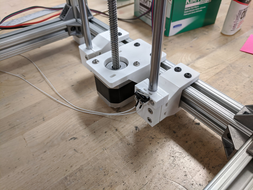 The picture below shows the third calibration cube I printed. This one has slightly better face features as it seems the layers are more on top of one another compared to the first cube. There still seems to be some error though which I think can be attributed to the linear rails and bearings as they are not of the highest quality. Furthermore, the extrusion multiplier should be adjusted because I think it's extruding a little too much plastic. The small nubs on all of the corners can hopefully be removed in the print settings as the slicer, Simplfy3D, has a feature, drift to end, which slows/stops the extrusion before it reaches an endpoint. 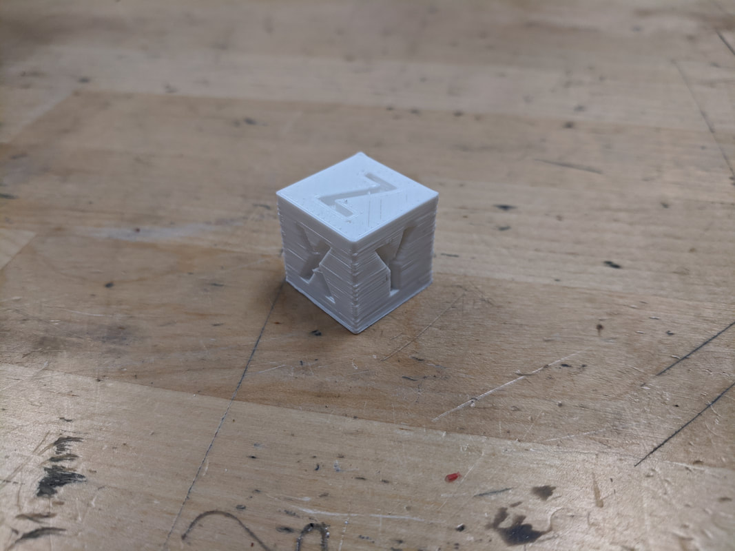
0 Comments
|
