|
Today, after replacing the stepper motor and readjusting the Z-axis home offset, I was able to try out my first print. I decided to print a calibration cube, as most people do, for the first print so I could see just how off things were. I still do not have the bed heater up and running so it was going to print on the cold glass. I was skeptical of if I would get any bed adhesion but was eager to try it. The first three perimeter layers did not adhere to the bed at all but the first layer infill did, which was surprising. The print was still useless, however, as the non-adhered plastic was now drifting with the nozzle and was most definitely going to jeopardize the rest of the print. I cleaned off the bed and applied some glue to the glass to get the first layer to stick. This time the first layer adhered perfectly. 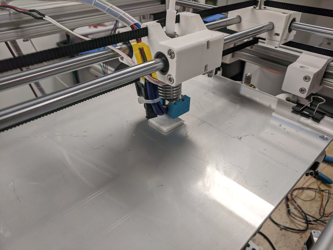 Here is the finished calibration cube: 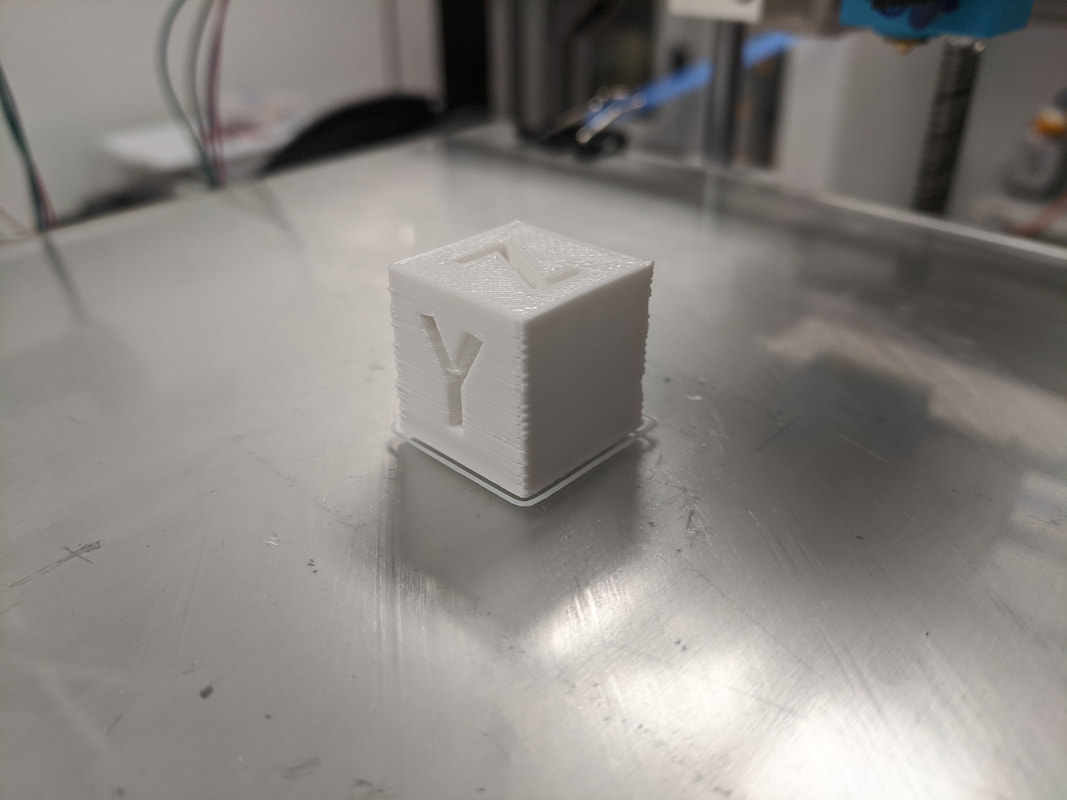 There is still a lot of work to do on all of the axes to bring the accuracy closer to what I want but I'm pretty happy with how this turned out for a first go. From the picture above you can see that it looks like each layer shifted slightly as the print went along. I think this could be the belts not being taught enough. Furthermore, the extruder stepper motor began slipping at one point during the print which I have conclude is because the filament feed rate was too high for the nozzle temperature I was running at. Mid print I bumped up the temperature ten degrees and the problem seemed to go away. The next step is to take a look at the XY-axis carriage system because I believe there can be some adjustments there and to get the heating bed going.
0 Comments
This is related to the last post. I pursued testing the control board further to hopefully solve my problems. The rest of the steppers moved so I was afraid that I had a bad extruder driver on the board. This would have been a real problem because the board I have has integrated drivers so I would have to replace the entire board to fix the problem. I tried some extra steppers I had lying around and those too did not move. The next step I took was to make a break out connector from an extra harness I had lying around as I wasn't quite satisfied I was reading the voltages properly before. I hooked up multi-meters to the break out and recorded the voltages from each of the pins. The driver in question seemed to be performing not out of the ordinary (Online sources showed that if the driver was bad, I would be getting no voltage on any of the four pins). Still the stepper would not move. I shut it down for the day and started entertaining the idea of purchasing a new board.
The next day I tried to see one more time if I could solve this problem before I spent money. I plugged the stepper in and noticed I was getting very erratic movement out of it but different than what was happening before. To further investigate, I plugged in a different stepper motor and everything began to work fine. As it turns out, the stepper motor I had purchased with the extruder kit was dead-on-arrival. However, the only explanation I have for why other stepper motors didn't work as well was that the bad stepper may have put the board into a weird logic state and as soon as the board was turned off and reset, that state was reset. I have had no other problems with it in the further tests I ran. After heating up the nozzle to the printer, it was time to test if I could feed plastic from the extruder. In short, I could not. The stepper motor would twitch or spin one way for a little and then randomly reverse directions. At first I thought the stepper motor could have been bad but after plugging it into one of the other axes and it spun just fine. The only other explanation would be that the stepper motor driver is fried which is entirely possible as this board came from an older printer that had a plethora of issues. To do some trouble shooting, I tested the pins with a multimeter but it proved inconclusive as I didn't really know what I was looking for voltage wise. The next step was to check an adjacent driver and check the voltages on those pins. The stepper motor does its micro stepping by varying the current going through the coils. I'm going to check the pin out again but then look at how the current is changing. The micro stepping should follow a sine wave and I hope that I'll be able to replicate that on an oscilloscope if I need to use one. Below is a diagram on how the coils are set up on a 4 wire stepper motor.  |
